To get more wavelength lasers, please contact our sales.
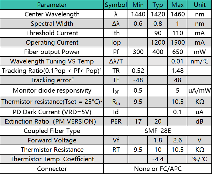
1. The tracking ratio is a measure of the front-to-back tracking when the output power is varied. On a plot of optical power versus back-face photocurrent, a straight line is drawn between the minimum power (30 mW) and the operating power (Pop) points. The tracking ratio is defined as the ratio between measured optical power (shown as data points on the plot) to the value derived from the straight line.
2. The tracking error is defined as the normalized change of output power relative to Pf at 25°C, that is, (Pf – Pf_25)/Pf_25, over case temperature range of 0 to 75°C, at constant back face monitor current corresponding to the lowest back face monitor current at Pf= Pop of 0°C, 25°C, 75°C.
3. Datasheet for Calculating Temperature from the resistance of the Thermistor is available now. You can contact us for details.
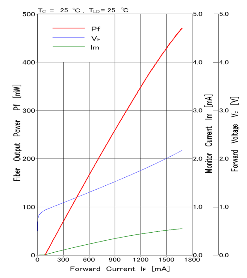
L-I Curve
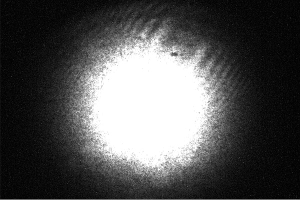
Digital Camera Analysis

|
1 |
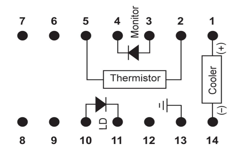
Thermoelectric Cooler (+) |
8 |
N/C |
|
2 |
Thermistor |
9 |
N/C |
|
3 |
PD Monitor Anode (-) |
10 |
Laser Anode (+) |
|
4 |
PD Monitor Cathode (+) |
11 |
Laser Cathode (–) |
|
5 |
Thermistor |
12 |
N/C |
|
6 |
N/C |
13 |
Case Ground |
|
7 |
N/C |
14 |
Thermoelectric Cooler (–) |
SMF-28E Fiber Nominal Characteristics and Tolerances
|
Parameters |
Specification |
|
Cut off wavelength |
1300nm |
|
Max Attenuation |
2.1dB/km |
|
Cladding Diameter |
125um |
|
Coating Diameter |
250um |
|
Core Cladding Concentricity |
≤0.5um |
|
Mode Field diameter |
9.5um |
Absolute Maximum Ratings
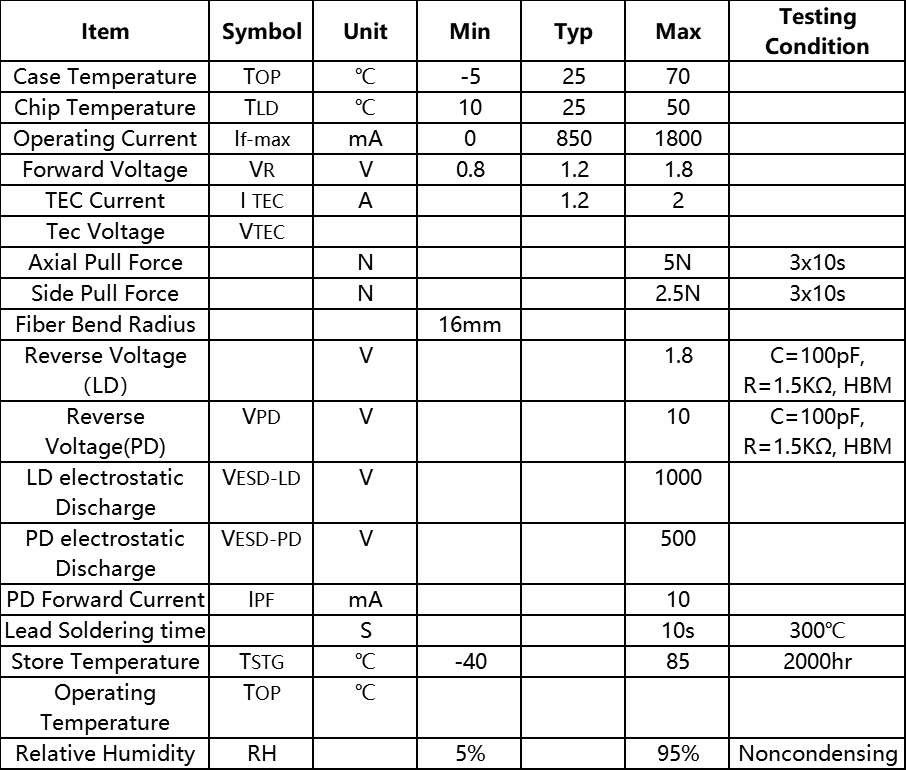
Absolute maximum ratings are the maximum stresses that may be applied to the module for short periods of time without causing damage and are listed in Table 5.Stresses in excess of the absolute maximum ratings can cause permanent damage to the device. Exposure to absolute maximum ratings for extended periods of time or exposure to more than one absolute maximum rating simultaneously may adversely affect device reliability. Specifications may not necessarily be met under these conditions.
Safety and Operating Considerations
The laser light emitted from this laser diode is invisible and may be harmful to the human eye. Avoid looking directly into the fiber when the device is in operation.
CAUTION: THE USE OF OPTICAL INSTRUMENTS WITH THIS PRODUCT INCREASES EYE HAZARD.
Operating the laser diode outside of its maximum ratings may cause device failure or a safety hazard. Power supplies used with this component cannot exceed maximum peak optical power. CW laser diodes may be damaged by excessive drive current or switching transients. When using power supplies, the laser diode should be connected with the main power on and the output voltage at zero. The current should be increased slowly while monitoring the laser diode output power and the drive current. Careful attention to heatsinking and proper mounting of this device is required to ensure specified performance over its operating life. To maximize thermal transfer to the heatsink, the heatsink mounting surface must be flat to within .001inch and the mounting screws must be torqued down to 1.5 in/lb. ESD PROTECTION—Electrostatic discharge (ESD) is the primary cause of unexpected laser diode failure. Take extreme precaution to prevent ESD. Use wrist straps, grounded work surfaces, and rigorous antistatic techniques when handling laser diodes.